EVS Powers
1 / 5
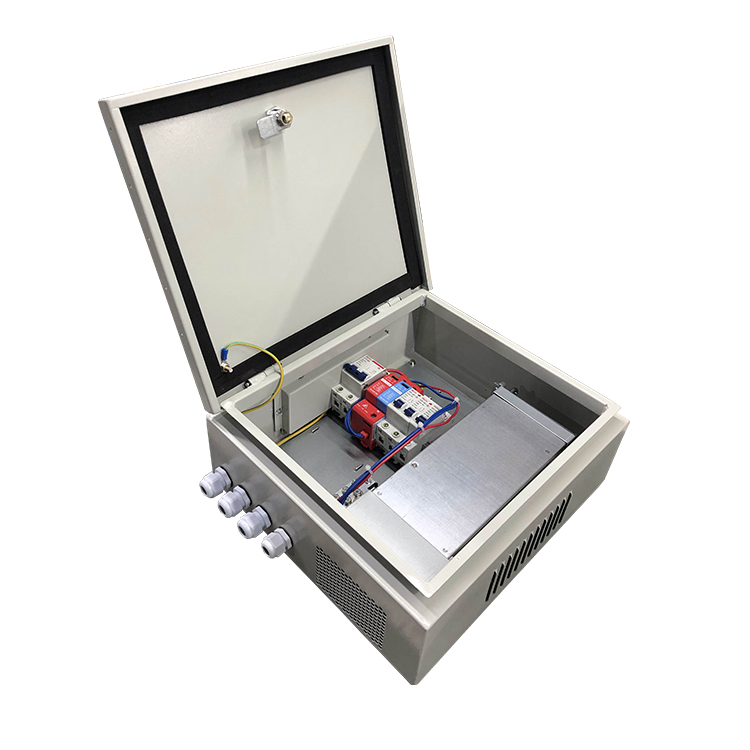
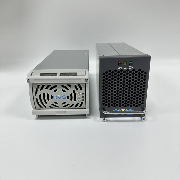
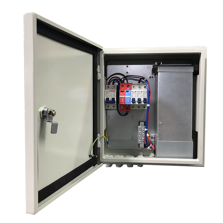
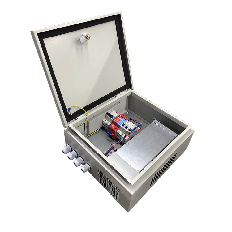
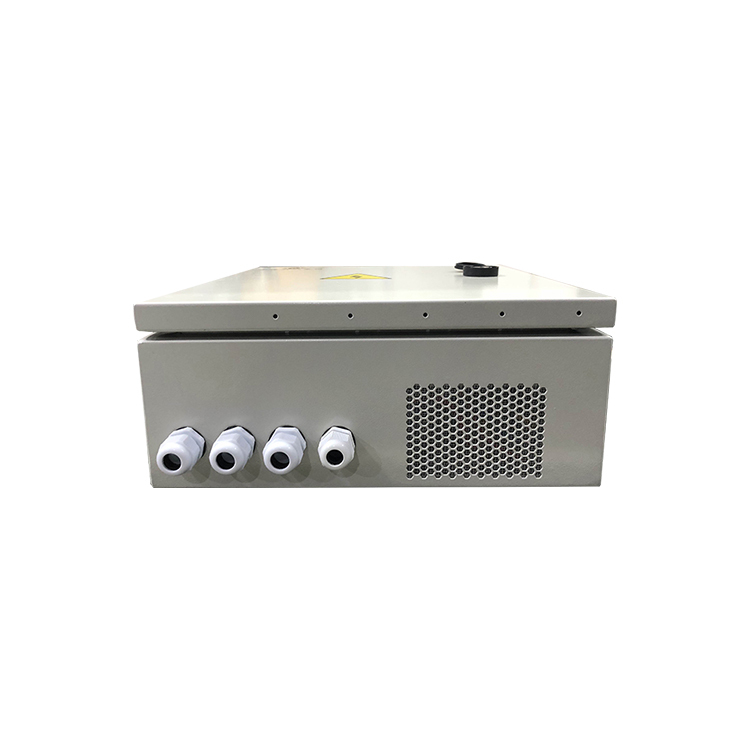
Industrial Power Supply System
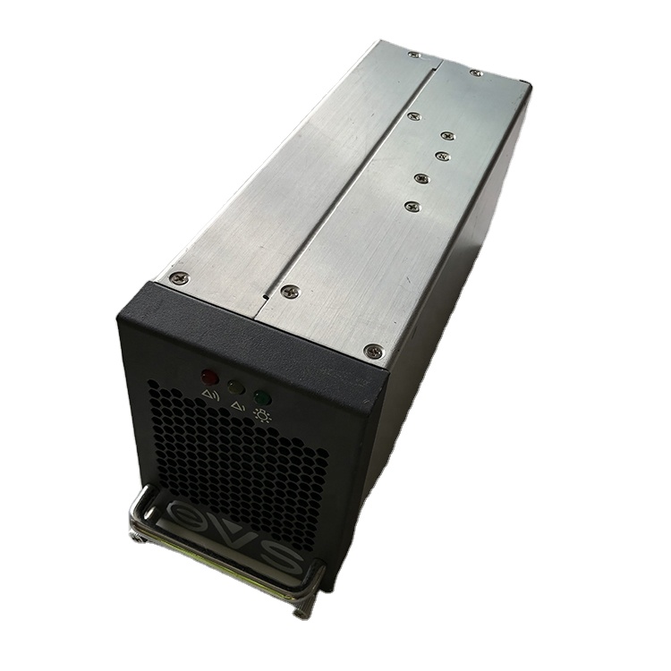
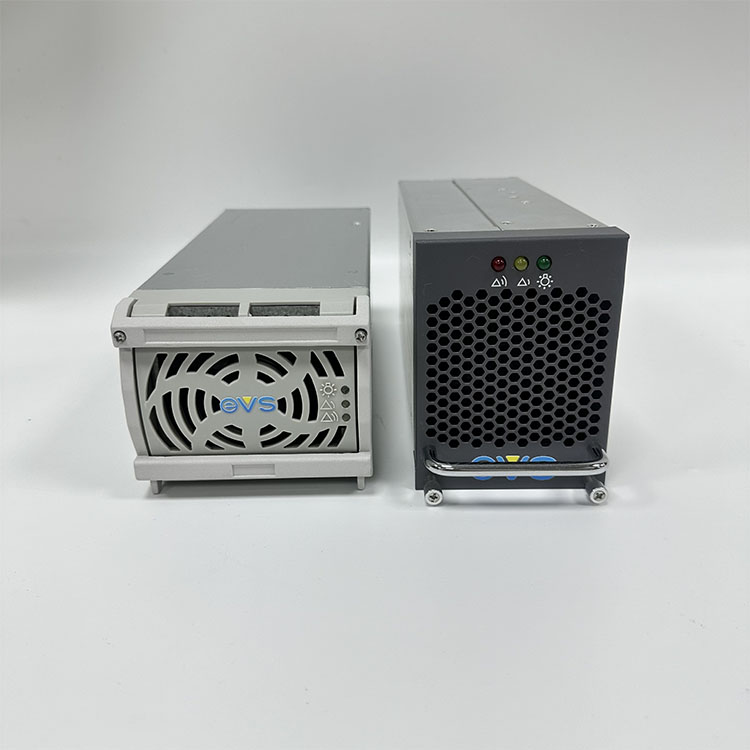
Designed for high-reliability communication infrastructure. Features an output voltage of 54V and output current range of 0-50A. Comprehensive safety built-in, including input over/under-voltage protection, output over-current protection, and output over-voltage protection.
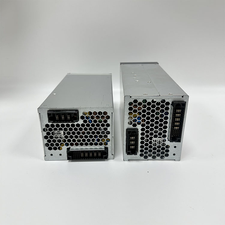
The rectifier module is one of the core components of a wall-mounted DC power supply panel. Its primary function is to convert AC power into DC power, typically utilizing advanced high-frequency switching power supply technology. This technology enables the rectifier module to achieve high conversion efficiency, effectively converting input AC power into stable DC power, providing reliable DC power for subsequent equipment. For example, in some communication base stations, the rectifier module converts AC mains power into a DC voltage suitable for communication equipment, ensuring its normal operation.
The monitoring unit acts as the "brain" of the wall-mounted DC power supply panel, monitoring the operating status of each component in real time. This includes monitoring the output voltage and current of the rectifier module, as well as the voltage, charge and discharge current, and remaining capacity of the battery pack. Using this data, the monitoring unit can promptly detect potential faults and issue alarm signals. Furthermore, it can control the rectifier module according to preset parameters, enabling intelligent management of the power supply panel. For example, when the battery pack's charge level is low, the monitoring unit can automatically adjust the rectifier module's output, increasing the charging current to the battery pack to ensure it remains in optimal working condition.
The battery pack serves as a backup power source for wall-mounted DC power panels during utility power outages. It typically utilizes lead-acid batteries or lithium-ion batteries. The battery pack's capacity varies depending on the application scenario and load requirements. Under normal circumstances, the rectifier module simultaneously charges the battery pack while supplying power to the load, keeping it fully or nearly fully charged. In the event of a utility power failure, the battery pack quickly switches over and continues to provide stable DC power to the load, ensuring uninterrupted operation of critical equipment. For example, in some power automation systems, when the grid fails, the battery pack can provide power to relay protection devices, automated monitoring equipment, and other components for several hours or even longer, preventing system failures and data loss caused by power outages.
Wall-mounted DC power panels are widely used in communications base stations. They provide stable DC power to communications equipment such as base station transceivers, transmission equipment, and monitoring equipment. Because communication base stations are widely distributed, many located in limited space such as rooftops and mountainous areas in cities, the space-saving and easy-to-install advantages of wall-mounted DC power panels are fully demonstrated. Furthermore, their high reliability ensures uninterrupted operation of the communication network, ensuring users enjoy stable communication services.
In automated substations and switchgear, wall-mounted DC power panels provide DC power to relay protection devices, automated monitoring systems, and signaling equipment. These devices are crucial to the safe and stable operation of the power system. Power supply problems can cause malfunctioning relay protection or monitoring system failure, leading to power outages. The reliability and stability of wall-mounted DC power panels meet the stringent requirements of power system automation equipment, ensuring the safe operation of the power system.
Wall-mounted DC power panels are also widely used in industrial automation production lines, elevator machine rooms, smart buildings, and other fields. In industrial automation production lines, it provides DC power for various control devices, sensors, actuators, etc., ensuring efficient and stable operation of the production line; in elevator machine rooms, it provides backup power for the elevator control system, lighting system, etc., ensuring that the elevator can operate safely when the mains power is interrupted, protecting the lives of passengers; in smart buildings, it provides DC power for the access control system, security monitoring system, fire alarm system, etc. in the building automation system, improving the intelligent management level and safety of the building.
| No. | Items | Technical Specifications | Unit | Remarks |
|---|---|---|---|---|
| 1 | Operation Temperature | -25 to +50 | °C | |
| 2 | Storage Temperature | -40 to +85 | °C | |
| 3 | Relative Humidity | 10 to 90 | % | |
| 4 | Cooling | Air cooling with self-fan | ||
| 5 | Altitude | 70 to 106 | Kpa | |
| 6 | Maximum Operating Altitude | 3000 | M |
| 1. Input Characteristics | ||||
|---|---|---|---|---|
| No. | Items | Technical Specifications | Unit | Remarks |
| 1.1 | Input rated voltage | 200 to 240 | Vac | |
| 1.2 | Input voltage range | 90 to 264 | Vac | |
| 1.3 | Input Current | ≤ 8 | A | Lowest input voltage, rated load |
| 1.4 | Input voltage frequency | 50/60 | Hz | |
| 1.5 | Power factor | ≥ 0.99 | Rated input voltage, rated load | |
| 1.6 | Input Shock Current | ≤ 30 | A | 264Vac |
| 2. Output Characteristics | ||||
| No. | Items | Technical Requirements | Unit | Remarks |
| 2.1 | Output Rated Voltage | 24 | Vdc | |
| 2.2 | Output current range | 0 to 60 | A | Input voltage: 176 to 264Vac |
| 0 to 30 | A | Input voltage: 90 to 175Vac | ||
| 2.3 | Output voltage range | 26.8 | Vdc | |
| 2.4 | Efficiency | ≥ 93.2% | 220Vac input, output 54Vdc/25A | |
| ≥ 90% | 110Vac input, output 54Vdc/95A | |||
| 2.5 | Output ripple & noise | ≤ 200 | mVp-p | Rated load, frequency band is limited to 20MHz |
| 2.6 | Turn-on output delay | 3 to 8 | S | Vin=220Vac |
| 2.6 | Output rising time | ≤ 200 | mS | Output voltage rises from 10% to 90%, rated load |
| 2.7 | Turn on/off overshoot | ≤ ±5 | %Vo | |
| 2.8 | Combined regulation | ≤ ±1% | ||
| 2.10 | Transient Response | Overshoot: ≤ ±5 | %Vo | 5%-50%-25% or 50%-75%-50% load change |
| Recovery time: ≤ 200 | μS | |||
| 2.11 | Phone weighed noise voltage | ≤ 2 | mV | |
| 2.12 | p-pk value noise | ≤ 400 | mV | 0 to 300KHz |
| 2.13 | Wide frequency noise voltage | ≤ 100 | mV | 3.4 to 150KHz |
| ≤ 30 | mV | 0.15 to 30000KHz | ||
| 2.14 | Disperse noise | ≤ 5 | mV | 3.4 to 150KHz |
| ≤ 3 | mV | 150 to 200KHz | ||
| ≤ 2 | mV | 200 to 500KHz | ||
| ≤ 1 | mV | 500 to 30000KHz | ||